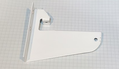
Shelf Bracket.
This is a much simpler, less expensive and easier-to-use bracket than the giant white triangles that everyone seems to sell.
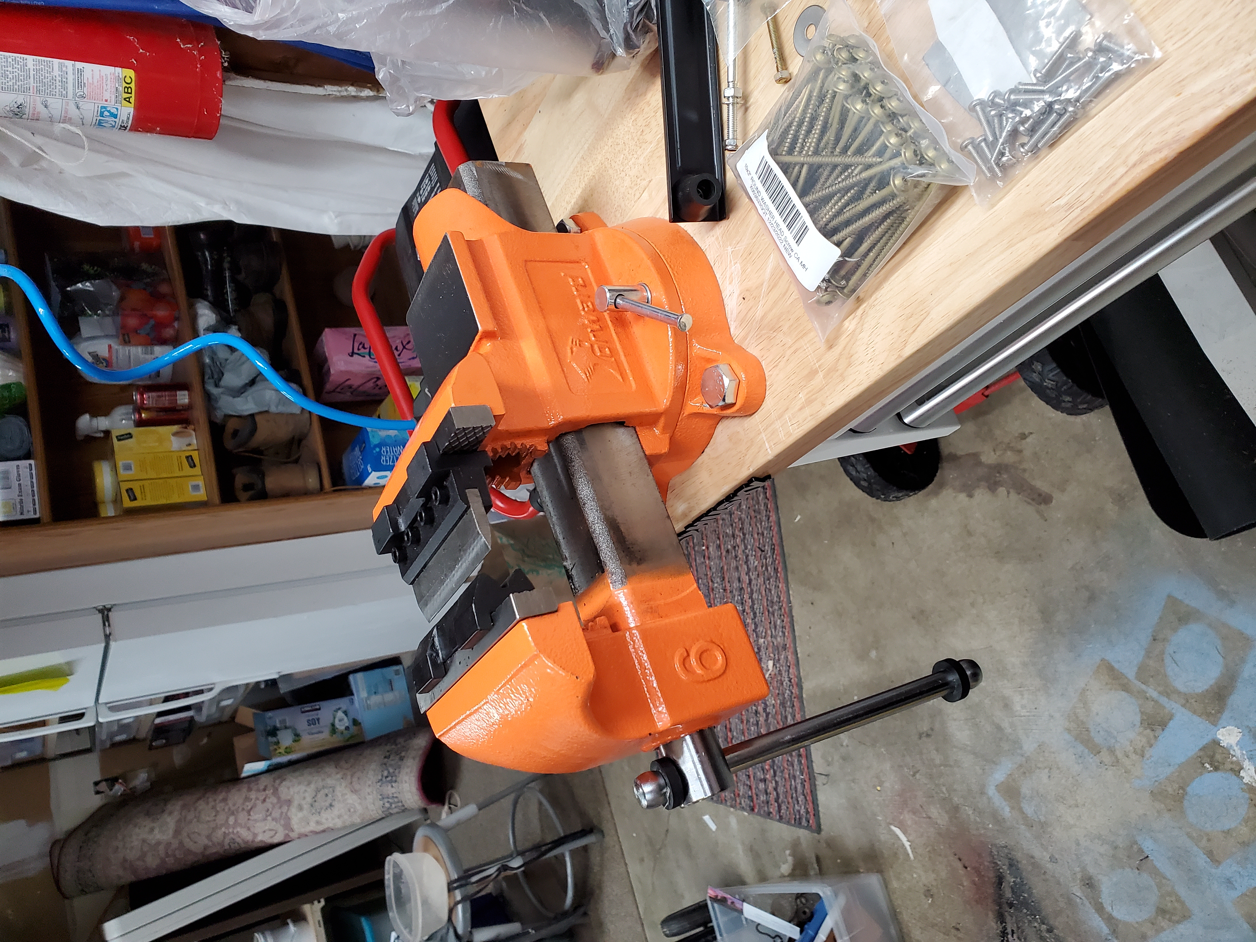
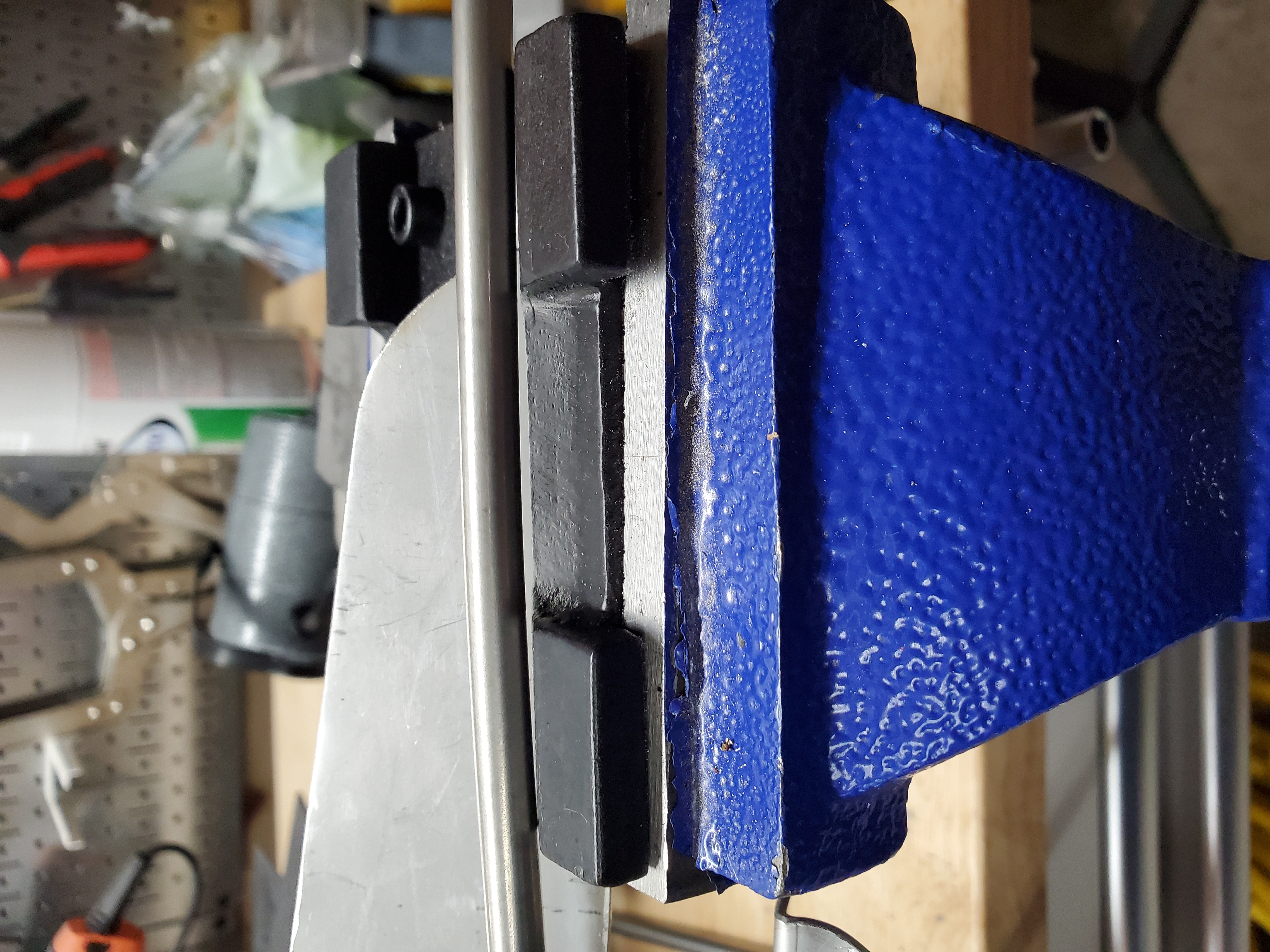
SEP 6 2023 I've had an idea how to get some more shelf space in both the garage and the laboratory, so I unwrapped the 10 brackets I ordered from back in January 2023, and then manually bent them using the orange vise, but this time with an extension to the vise handle, which is easier to trn than just the handle by itself. The handle is a post from a disused monitor mounting system which used to attach to a desk or table using a clamp, allowing a monitor to be attached to an arm which is in turn attached to the post.
Remembering how to scribe each bracket, and in which order an orientation to "brake" them is non-trivial.
All bent. Some of them needed a bit of persuasion, which you can see as dents where I pounded them to get better right angles. Getting the bends to be 90° manually is tricky. The vice-brake tends to either over-bend or under-bend, and it's hard to see the workpiece let alone measure it for squareness until AFTER it's out of the vice.
I don't have enough space for a proper permanent paint booth, so I'm trying this tent-like portable paint booth. I salvaged some cut coat-hangers I used for Varathane-dipping wooden pieces for another project and am using them here to suspect the brackets. I'm using TODO appliance paint (again?) to manually spray them.
I'm using TODO appliance paint (TODO again?) to manually spray them.
FEBRUARY 4 2023 Now to do the opposite wall in the closet. I've got one huge advantage for this new shelf.
All the mistakes I made with the first shelf. For one thing, I measured wall-to-wall, but the narrowest part of the
wall is right in the corner (due to the inside corner protector underneath the drywall there). So this time I measured
using that dimension and got a shelf that fit the space much better, and was therefore easier to put in place.
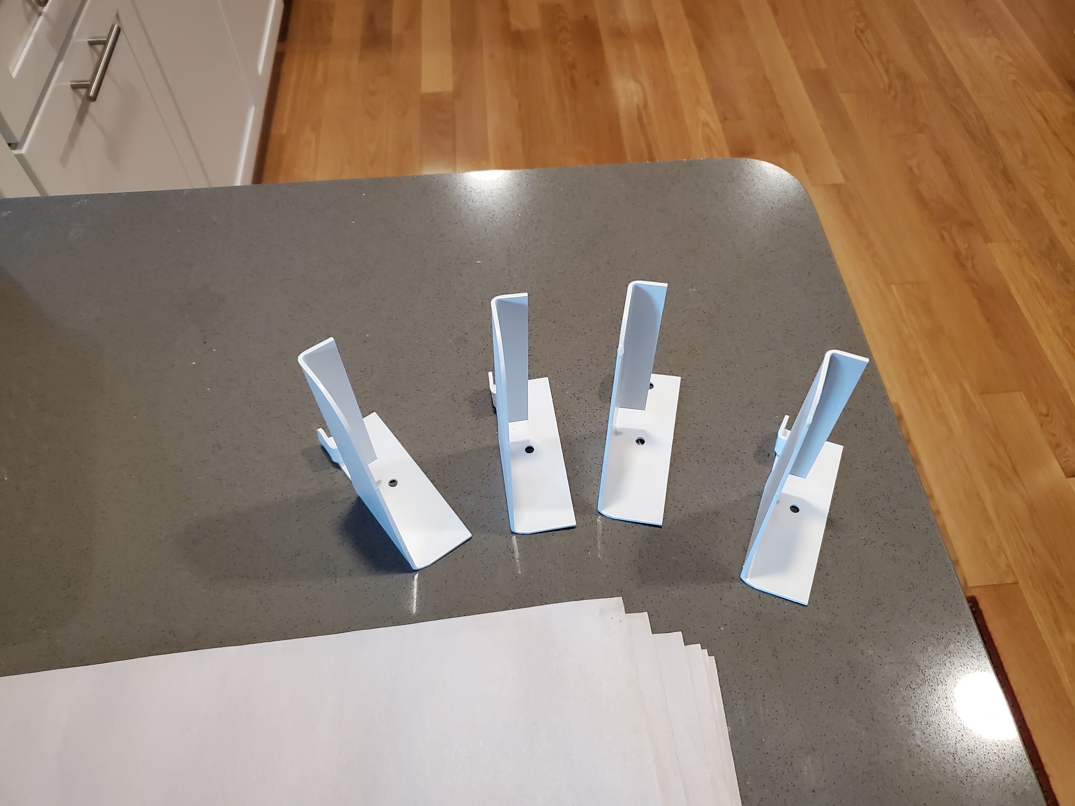
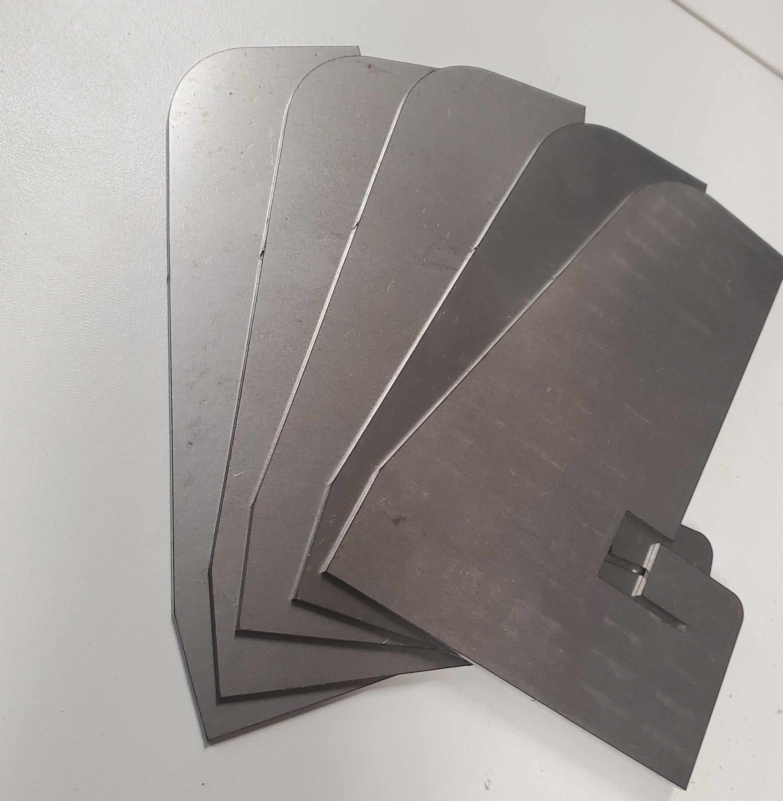
Here are the four finished brackets I'm going to use.
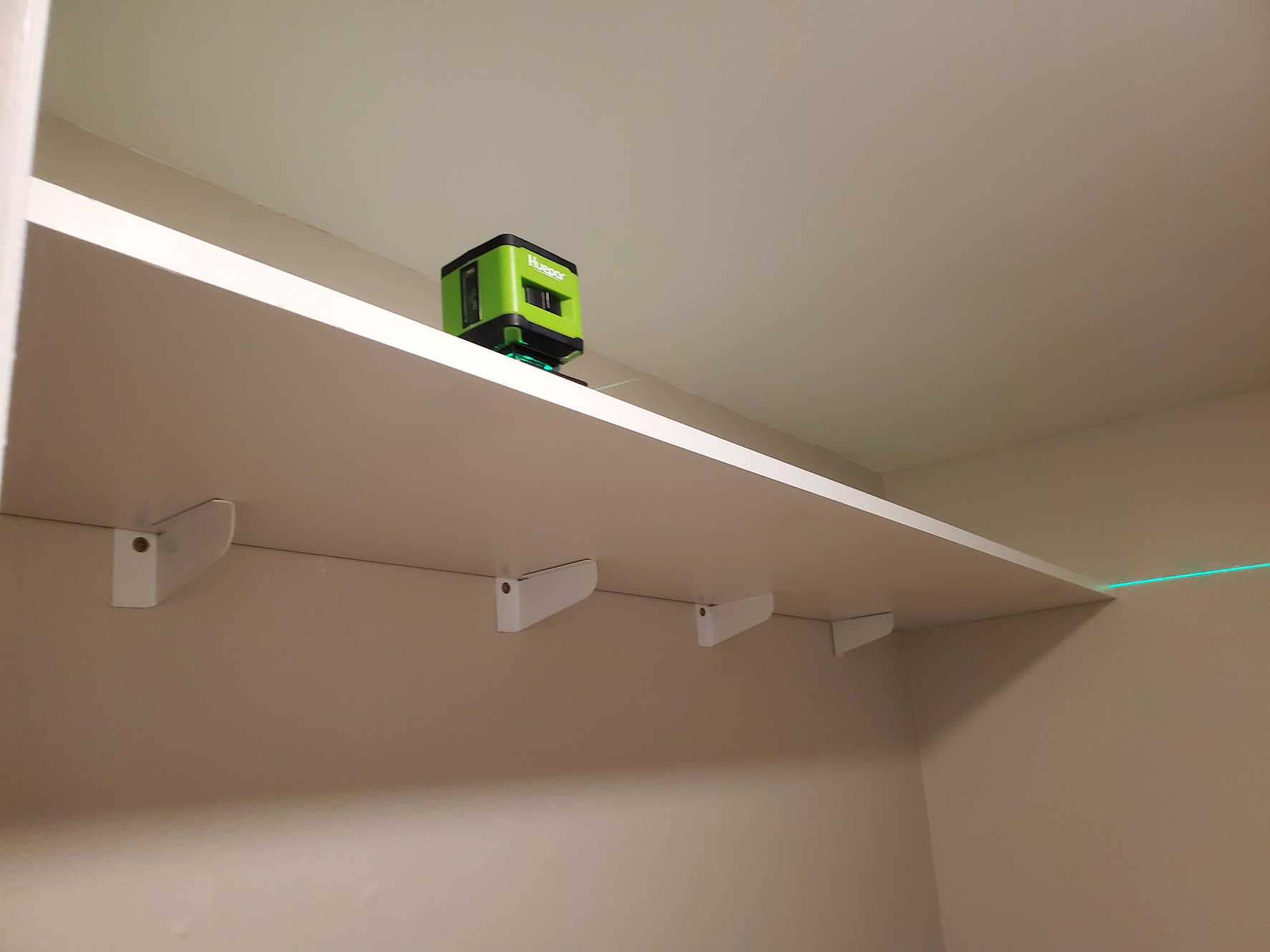
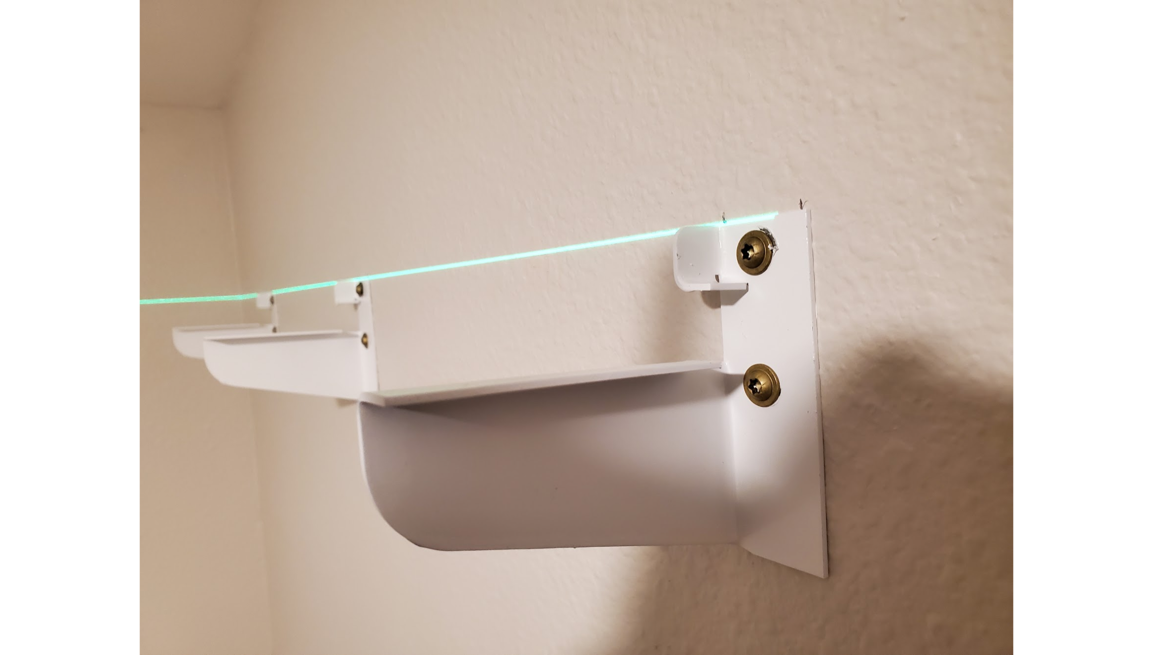
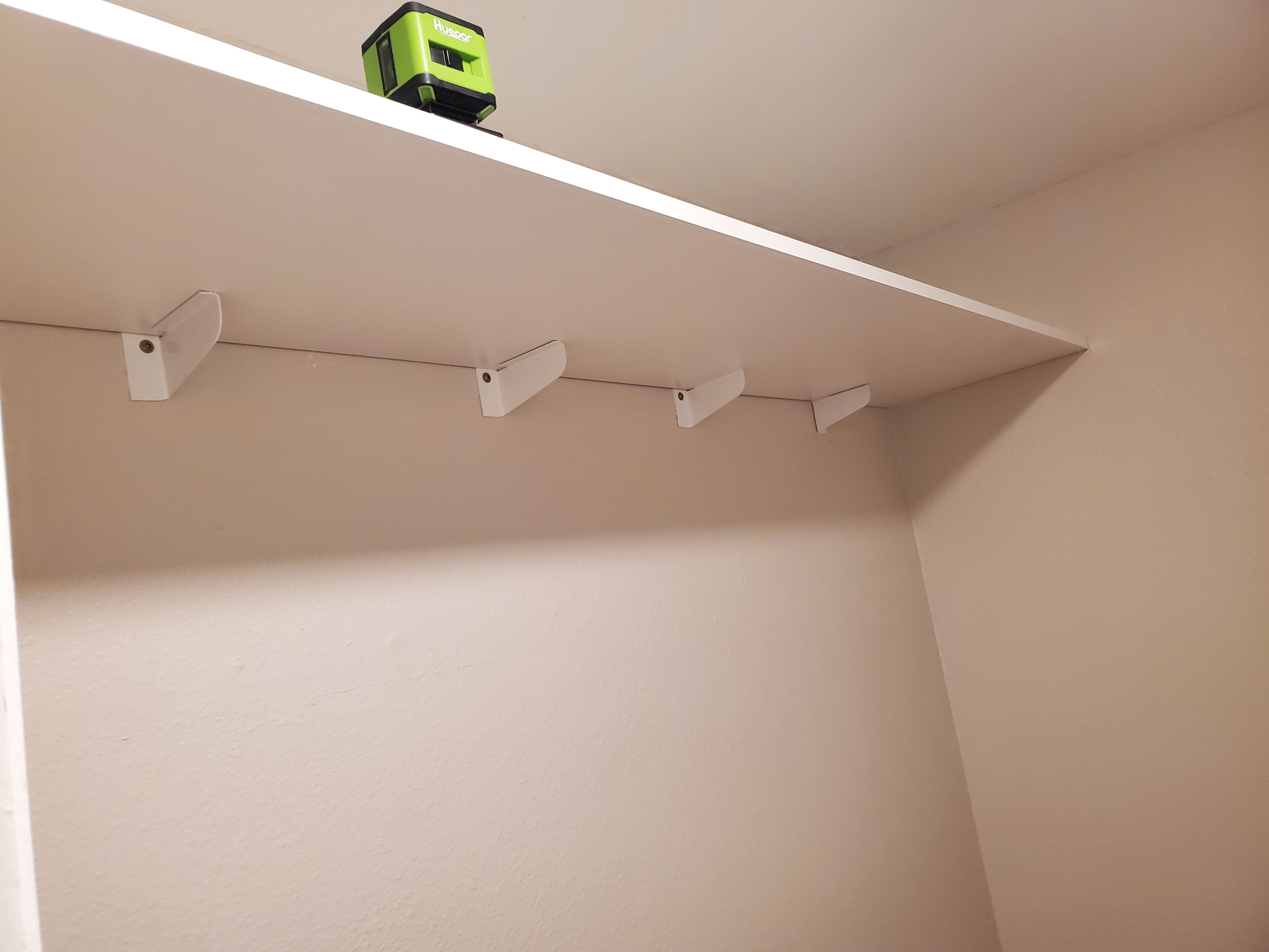
I mentioned before the happy accident of the laser level. Here's what it looks like with the laser turned on.
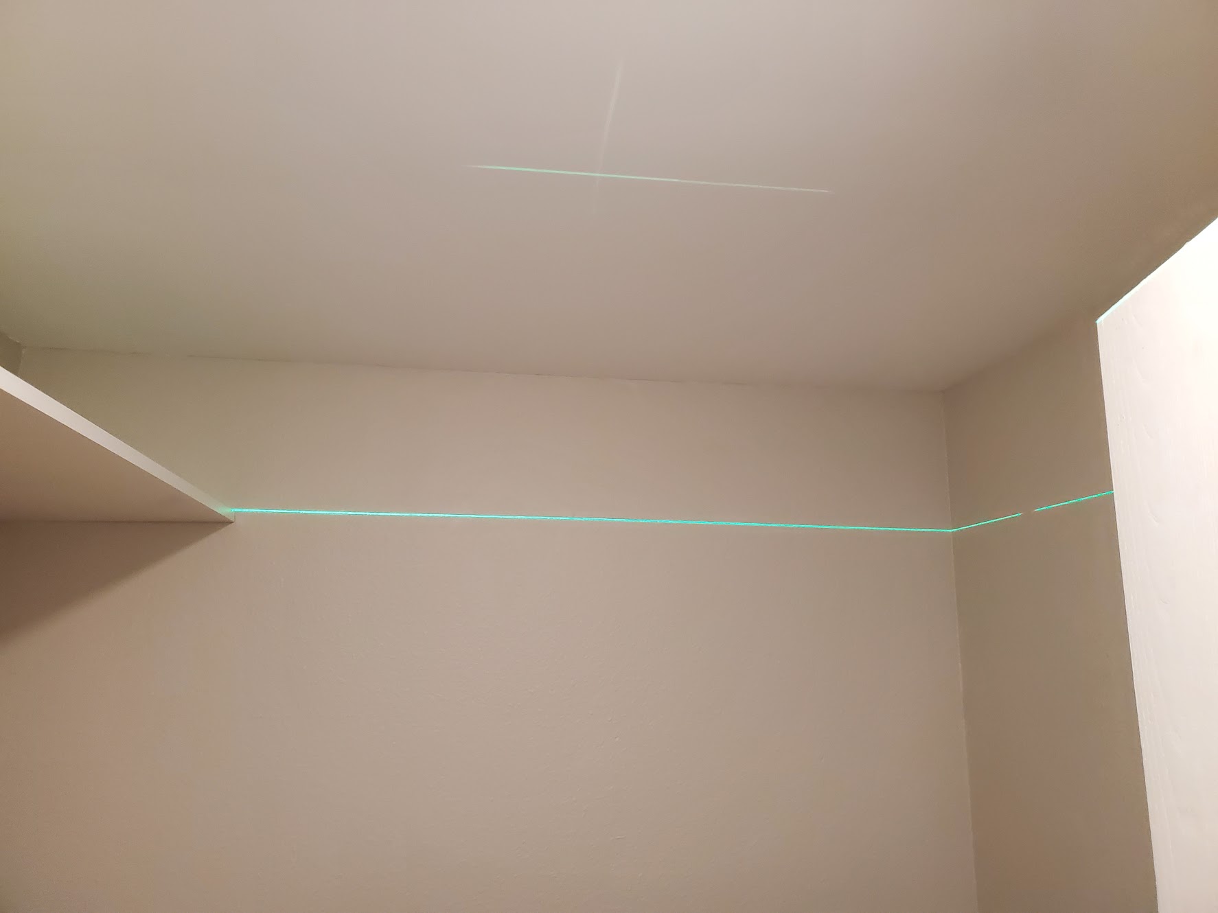
Moving clockwise around room, here's the back wall with the laser turned on.
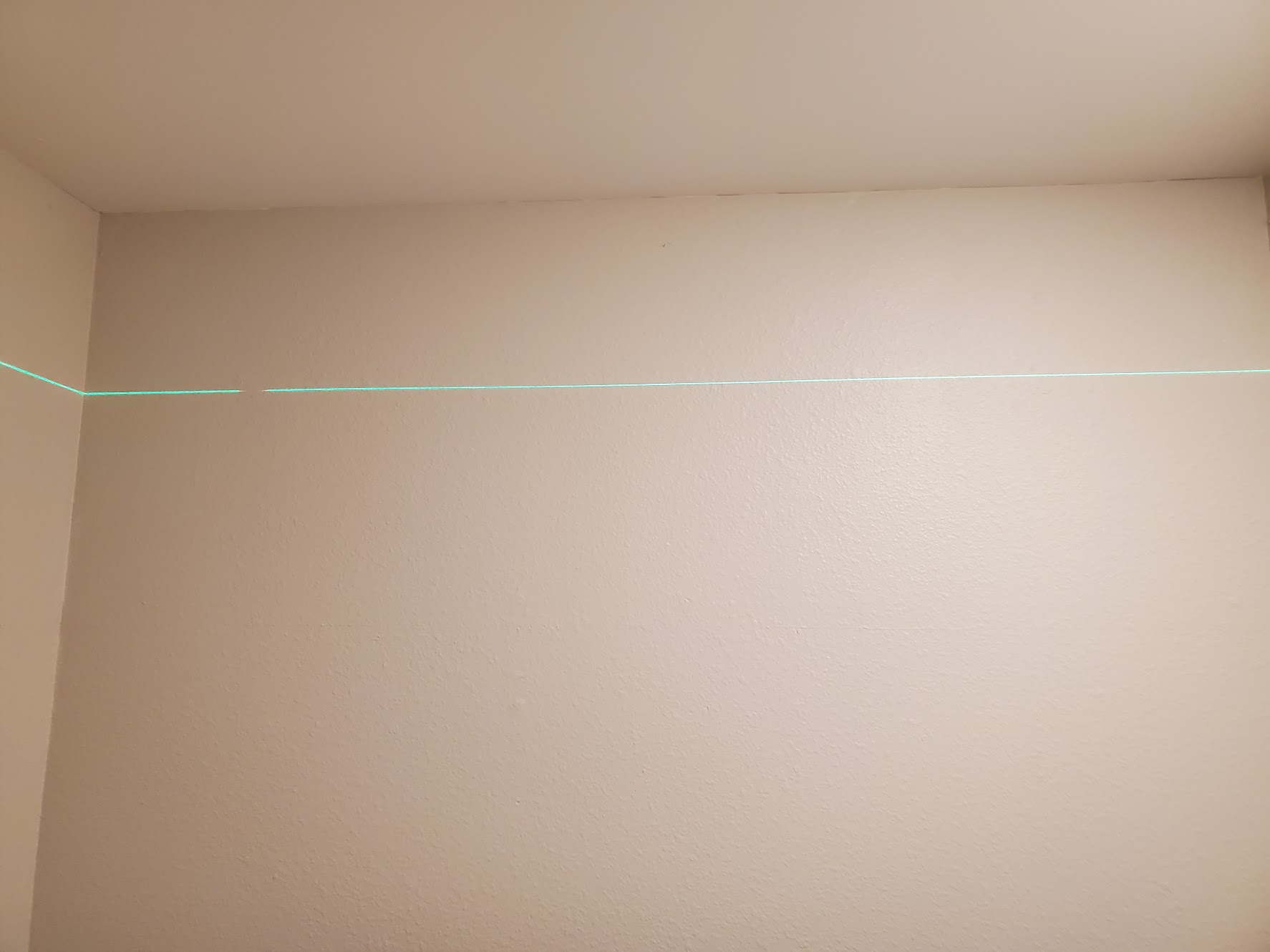
And here's the right wall, the destination of the new shelf.
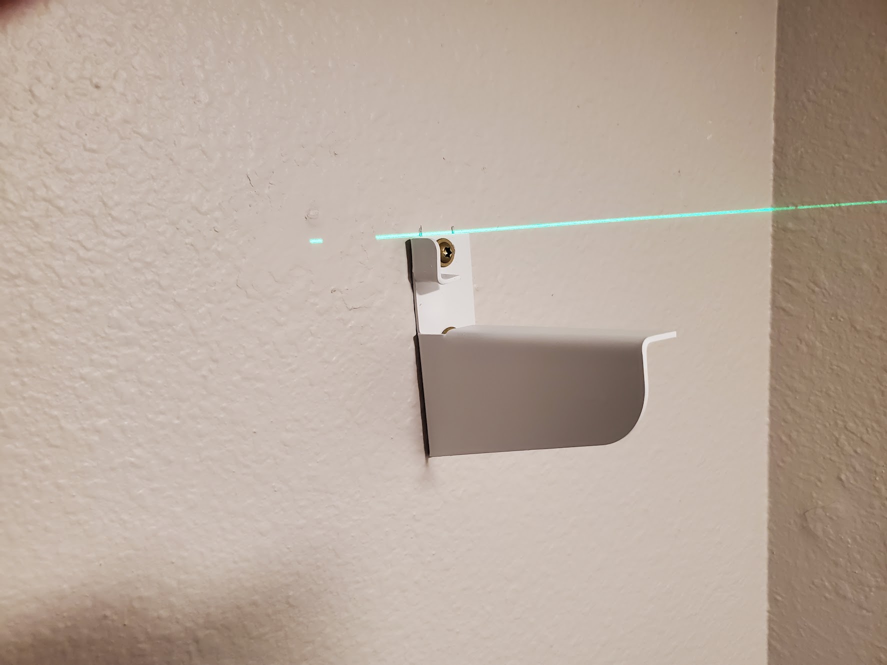
And here's the right-most bracket, now mounted to the destination wall. Impact drivers are a game changer, as are Torx screw heads. I hope never to have to use another philips or flat-head screw in my life.
I realize the camera angle makes this look kind of mis-aligned, but I promise it really isn't.
Here's what the other three brackets look like. It's kind of an odd angle, but you can see them if you look carefully.
I suppose if I were very clever, I would have taken a picture that showed the entire shelf, but a closet door got in the way. So here's one half of the new shelf.
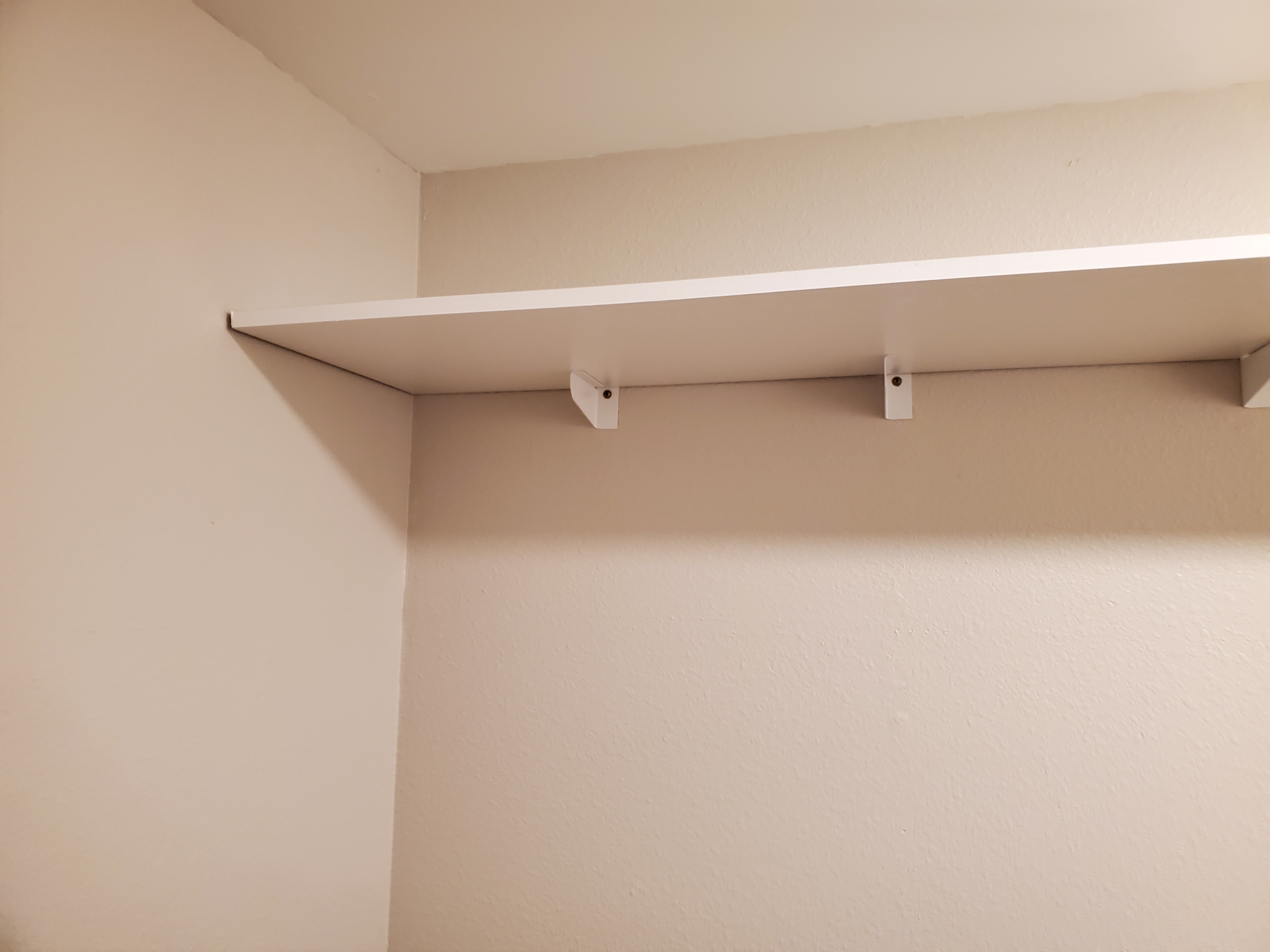
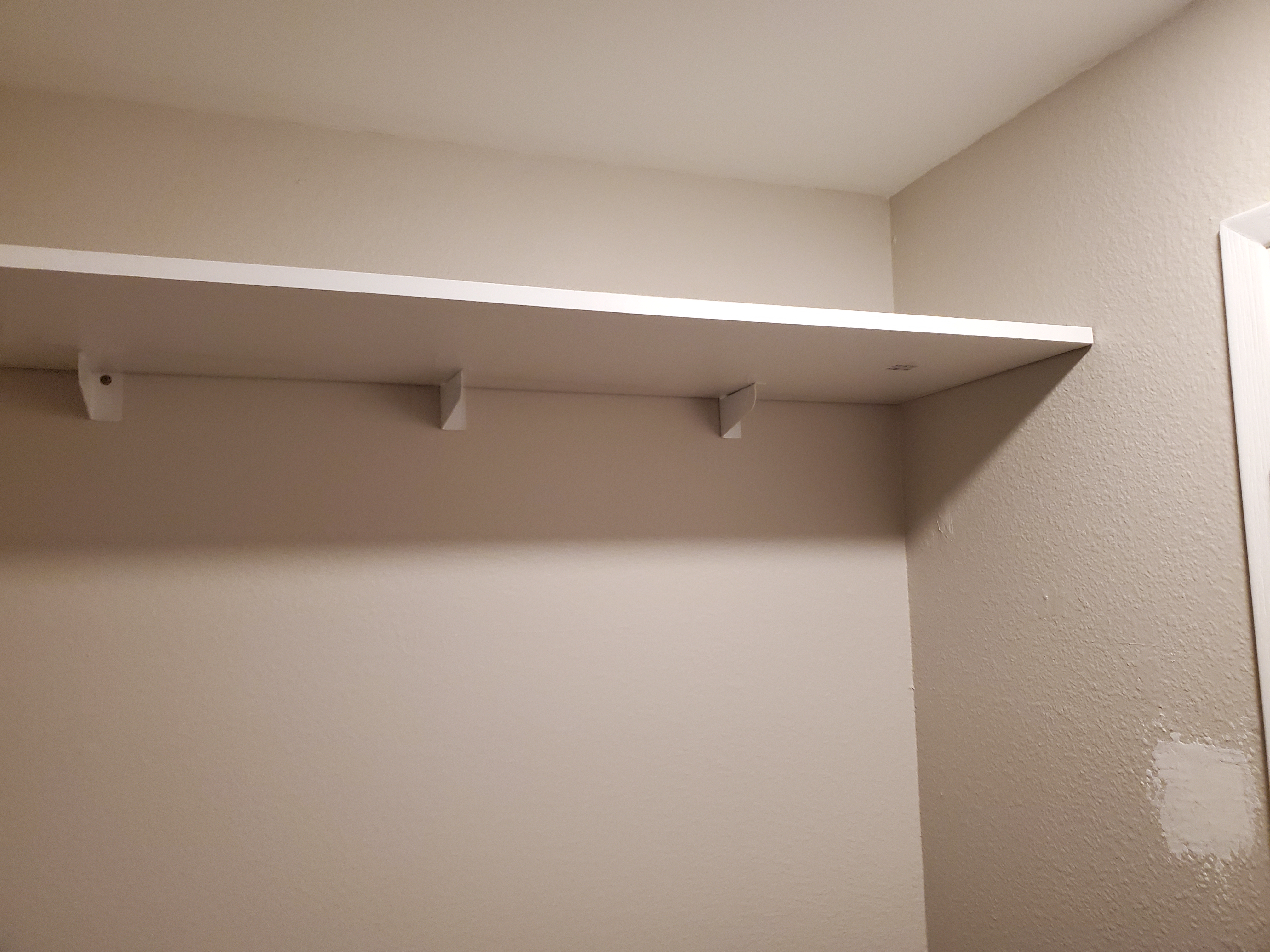
And there's the other half.
And here's a gnarly video showing the whole thing.
Not too shabby.
JANUARY 29 2023 Time for the first application - the master closet. There's a whole saga associated with getting these first four leveled and affixed to the studs, but the result is decent. I was able to hang my entire weight (250lbs) from the edge of the shelf, so that's satisfactory.
Now for the flaws. These are all "left-handed" except the right-most bracket. "Right-handed" means that I can hold the bracket against the wall with my left hand and the impact driver in my right. I'll make sure that all the future brackets are right-handed. Having them left-handed made them harder to work with.
Happy accident! Turns out that the top of each bracket aligns exactly with the laser level sitting at the edge of the shelf. That means when I do the opposite wall next, I can align those brackets using the laser level.
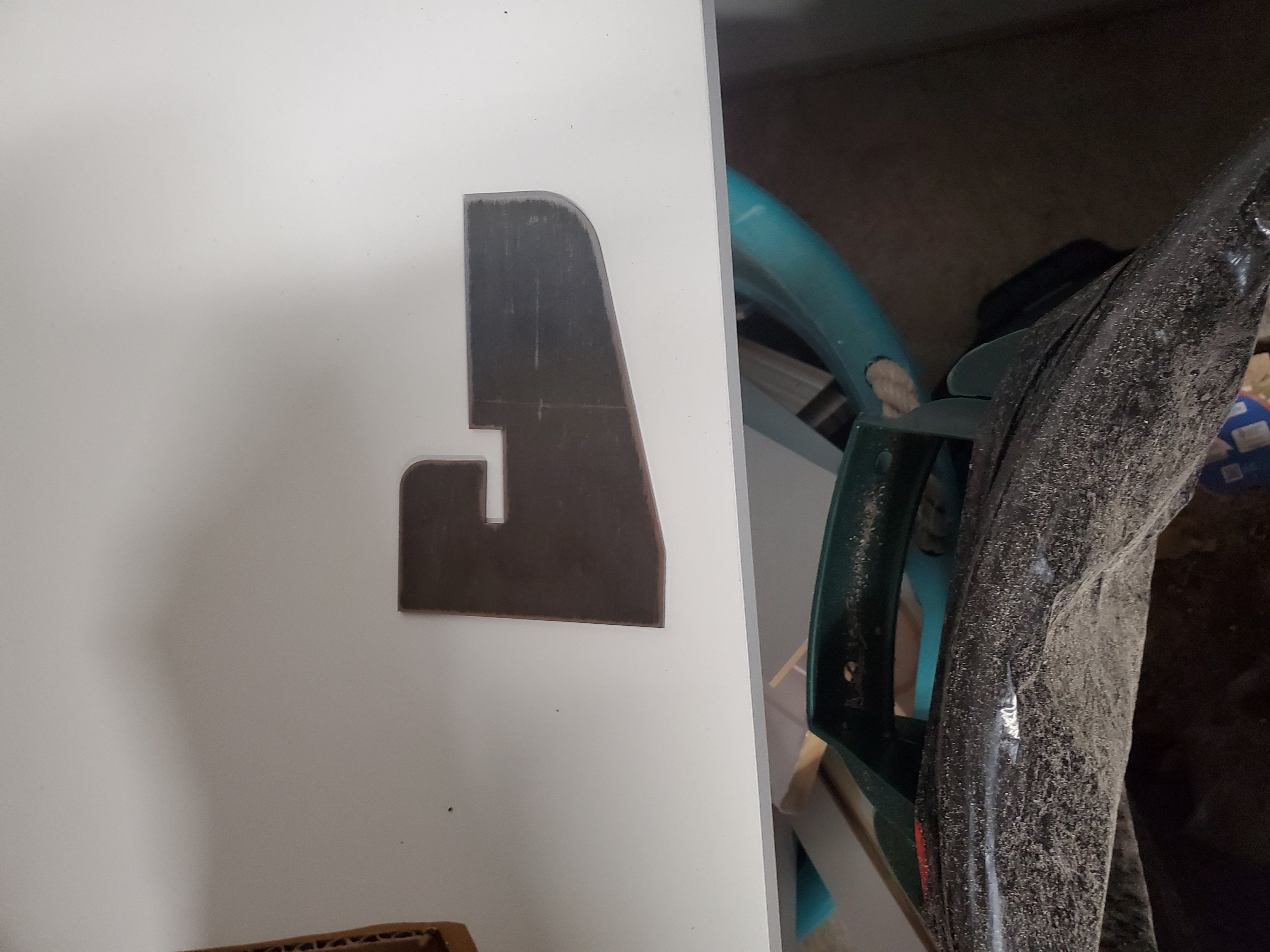
Design improvement I could drill a small hole at the end of the bracket farthest from the wall through the "lip" of the bracket so I can put a small screw to hold that end of the bracket in place. I anticipate one of the main failure-modes will be that downward pressure from the shelf causes the perpendicular portion of the bracket to slide left or right.
Design improvement I could put a 2° bend concave towards the wall in the vertical member of the bracket to ensure a completely snug fit with the wall.
Future task Conduct FMEA (Failure Modes and Effects Analysis) and formal stress analysis on the design.

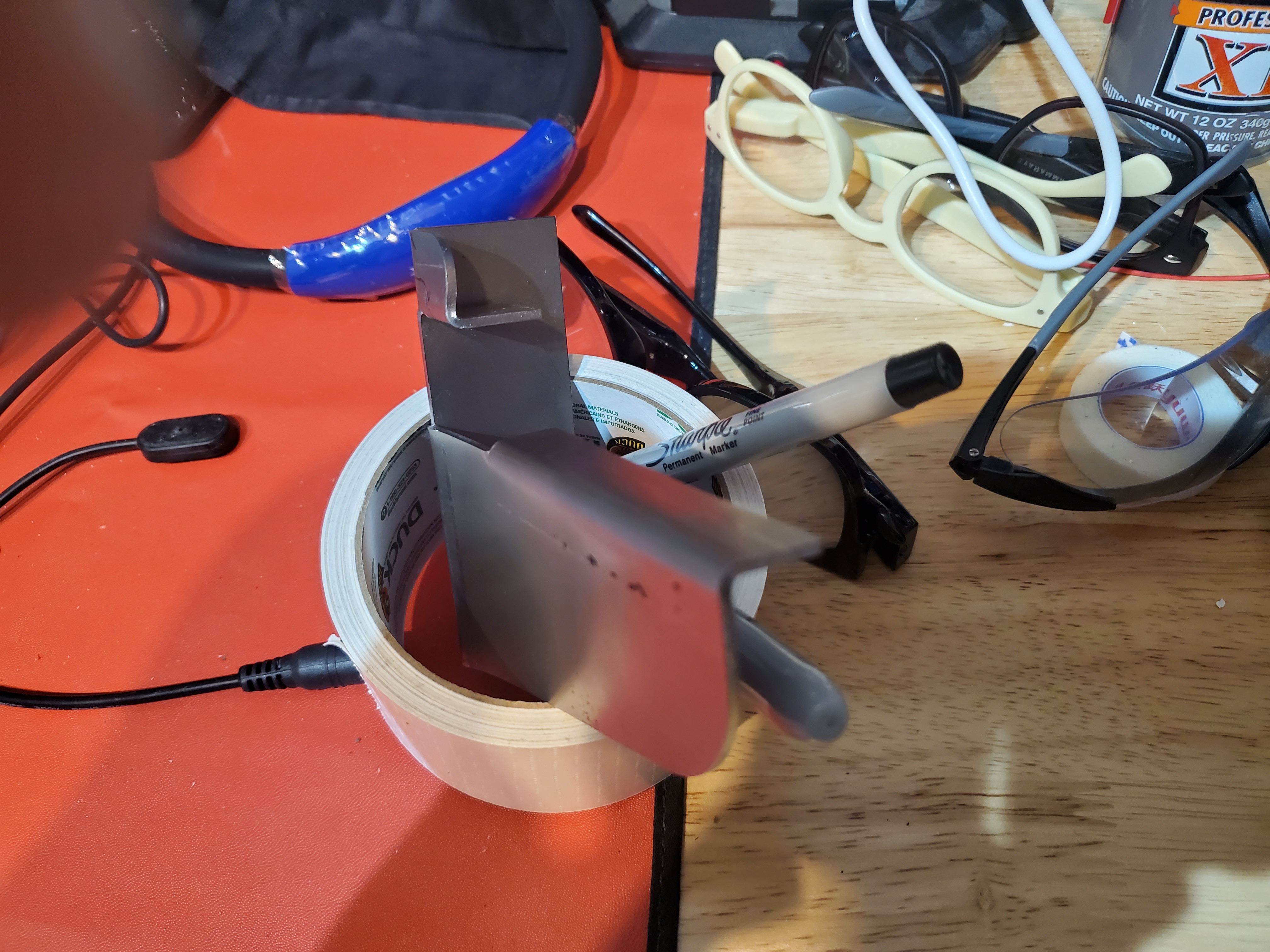
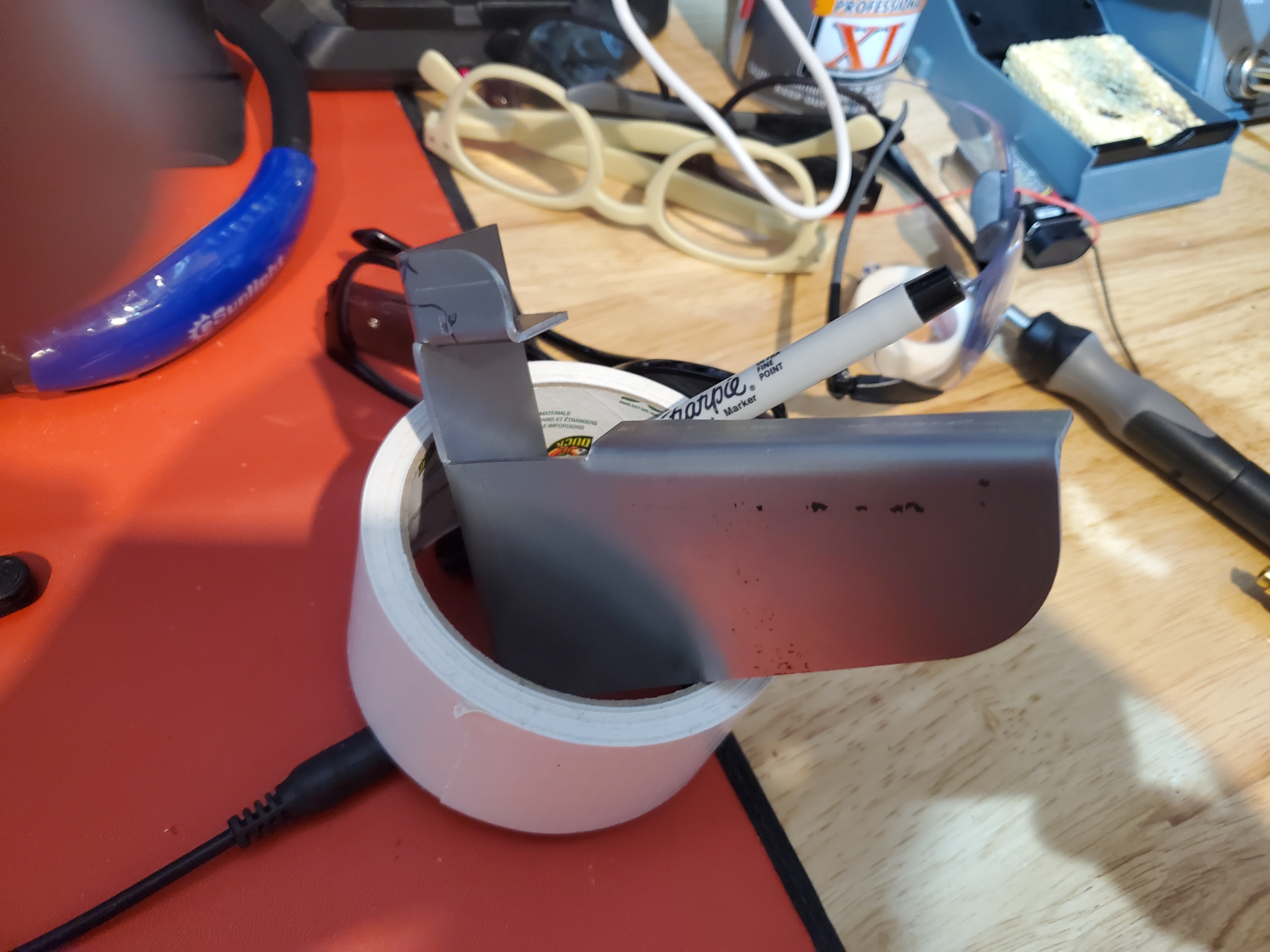
Design improvement I could put one or two bracing dimples in the long part of the vertical bend (from the wall side) to create little cross-braces to hold the support perpendicular to the wall.
See the example to the left.
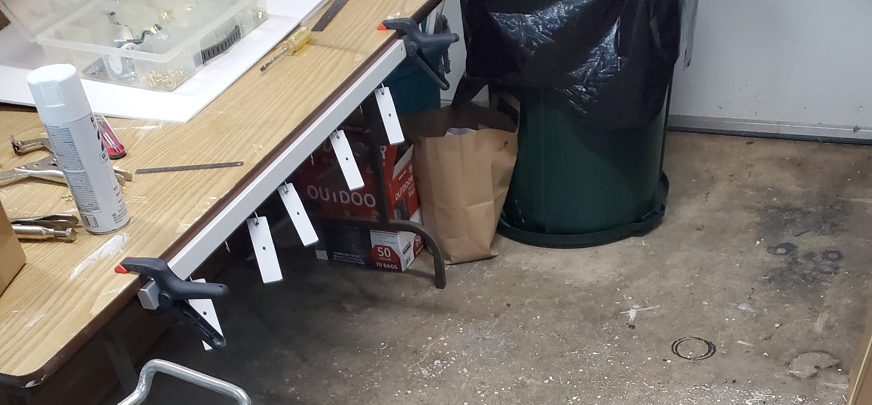
JANUARY 26 2023 Now that they're all bent properly (and all right-handed), I need a way to paint them.
I can't hang them anywhere under the open garage door, so I made a little array of hooks and clamped it underneath
the folding table in the garage.
This is what the first coat looks like.
JANUARY 23 2023 Let's get to work on the first batch of these for the bedroom closet shelves.
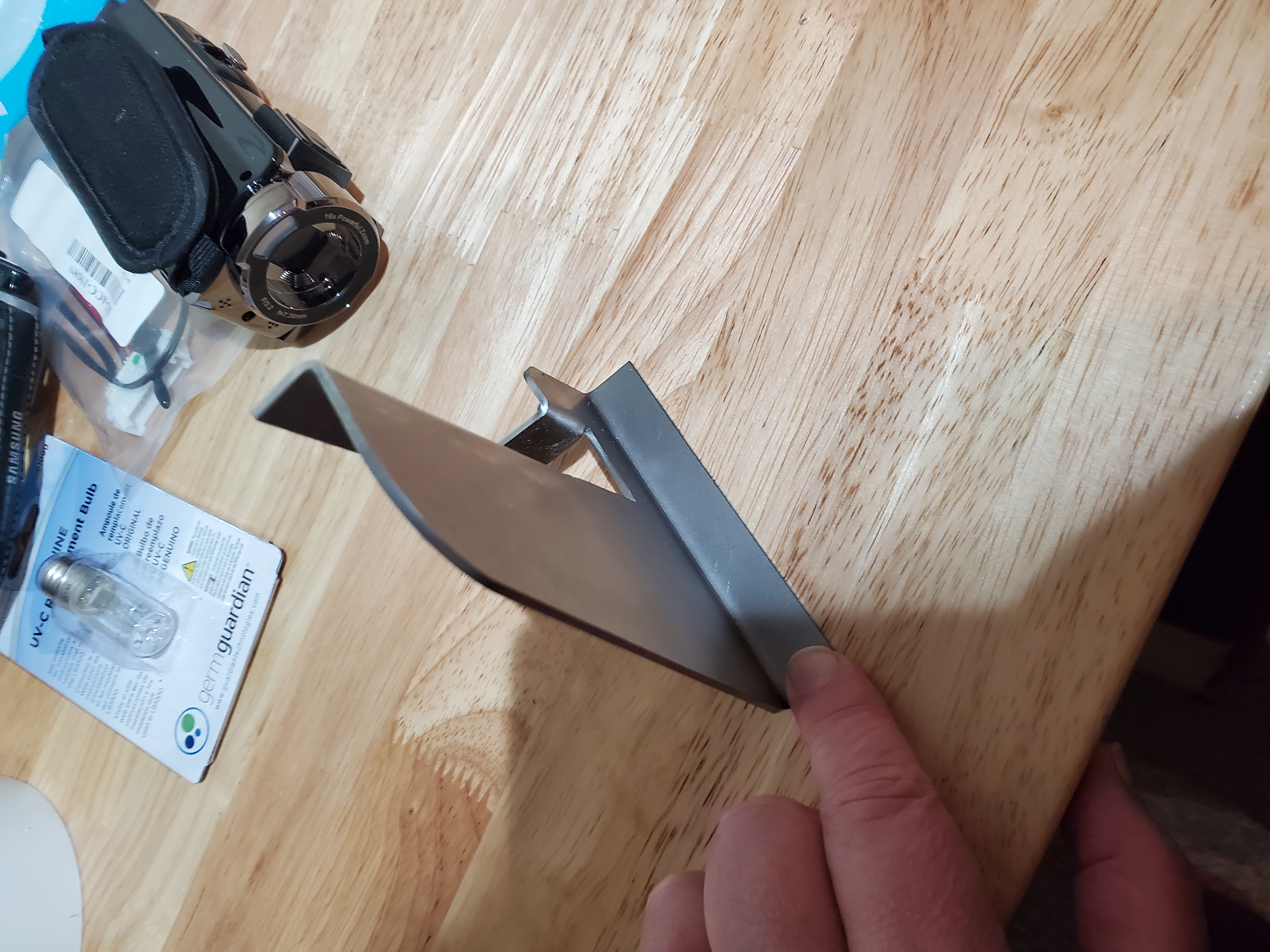
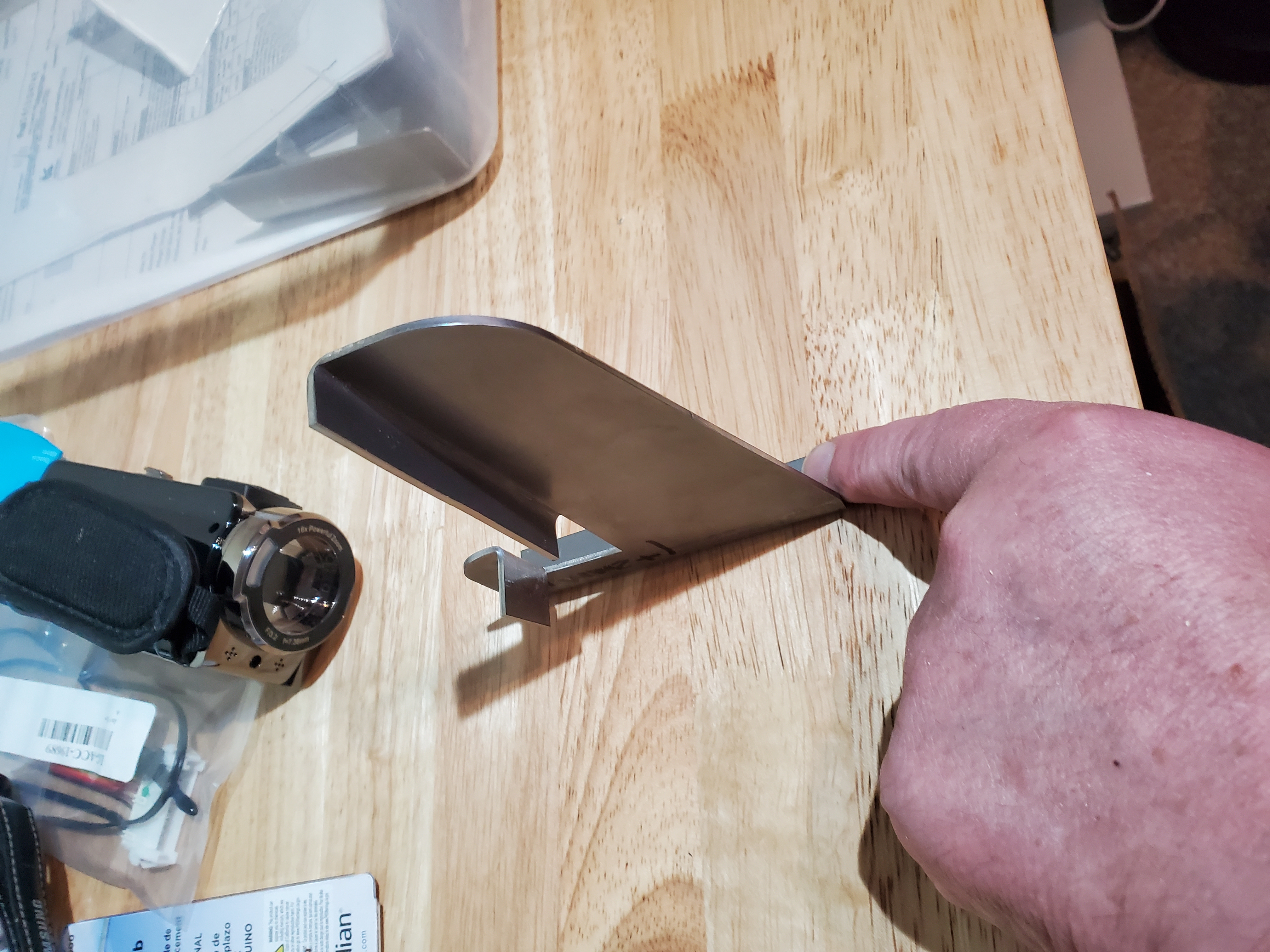
First we have to bend them with the new vise. Here's what the first one looks like after bending. So you would hold the bracket in your left hand. Line up the top flange with the line on the wall where you want the bracket to go, and then drive in two screws (holes not yet drilled).
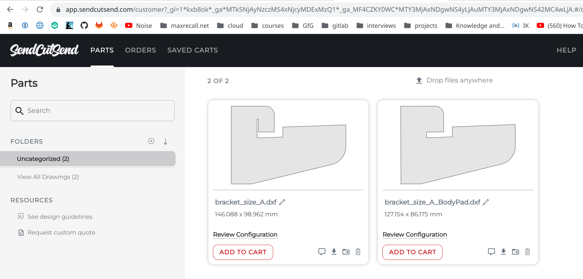
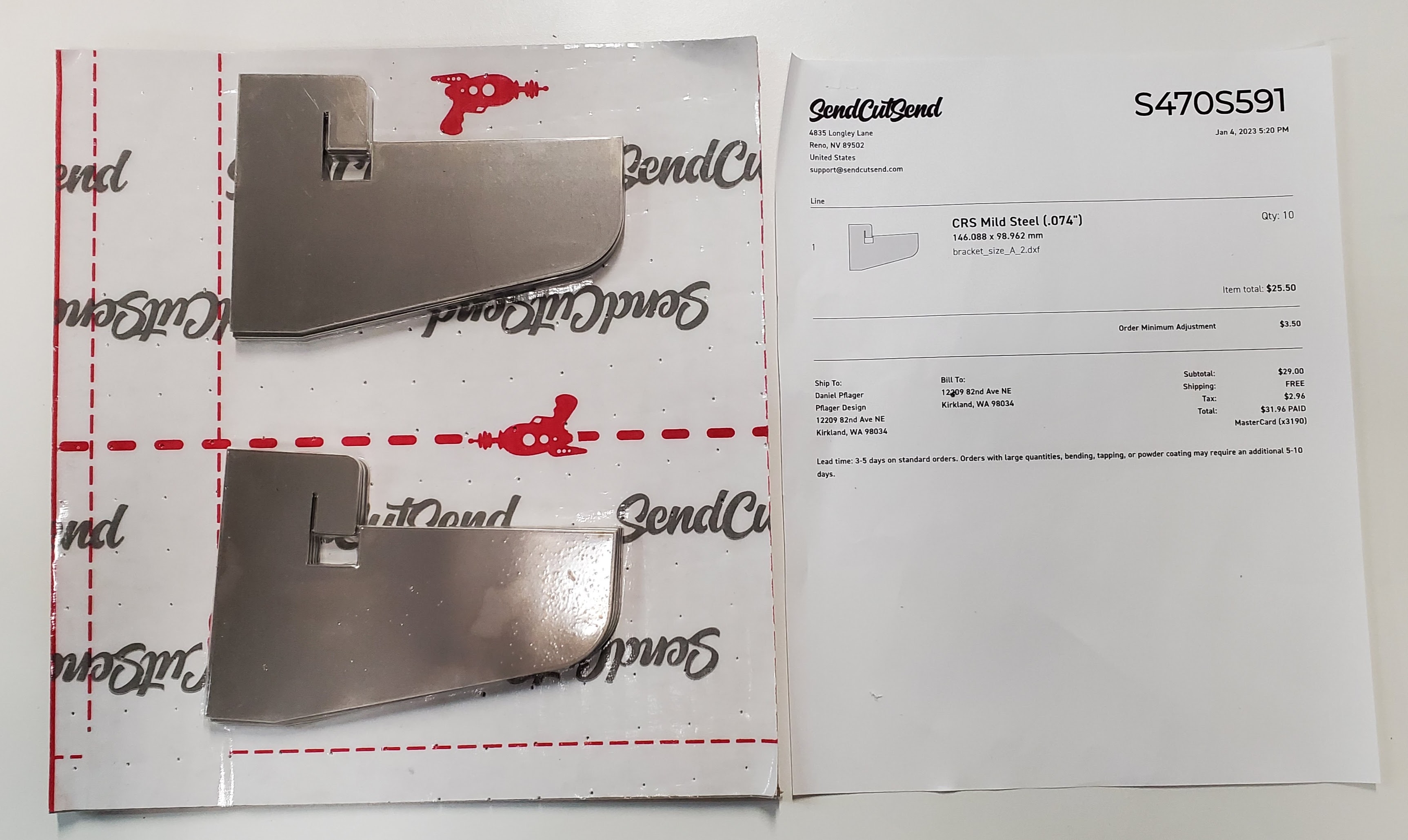
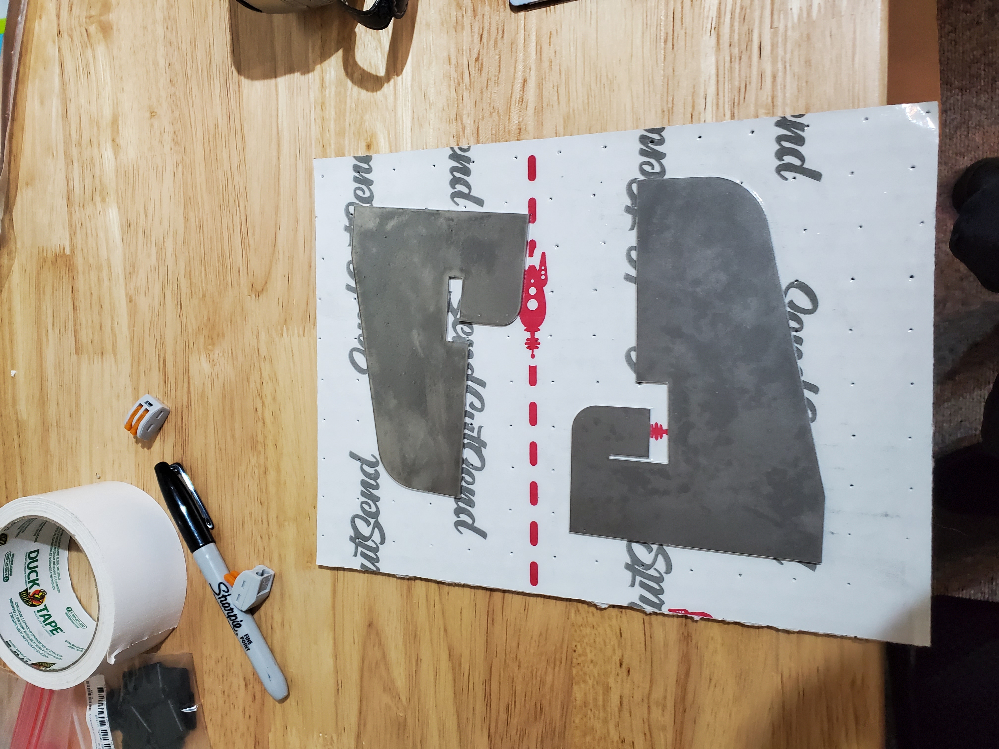
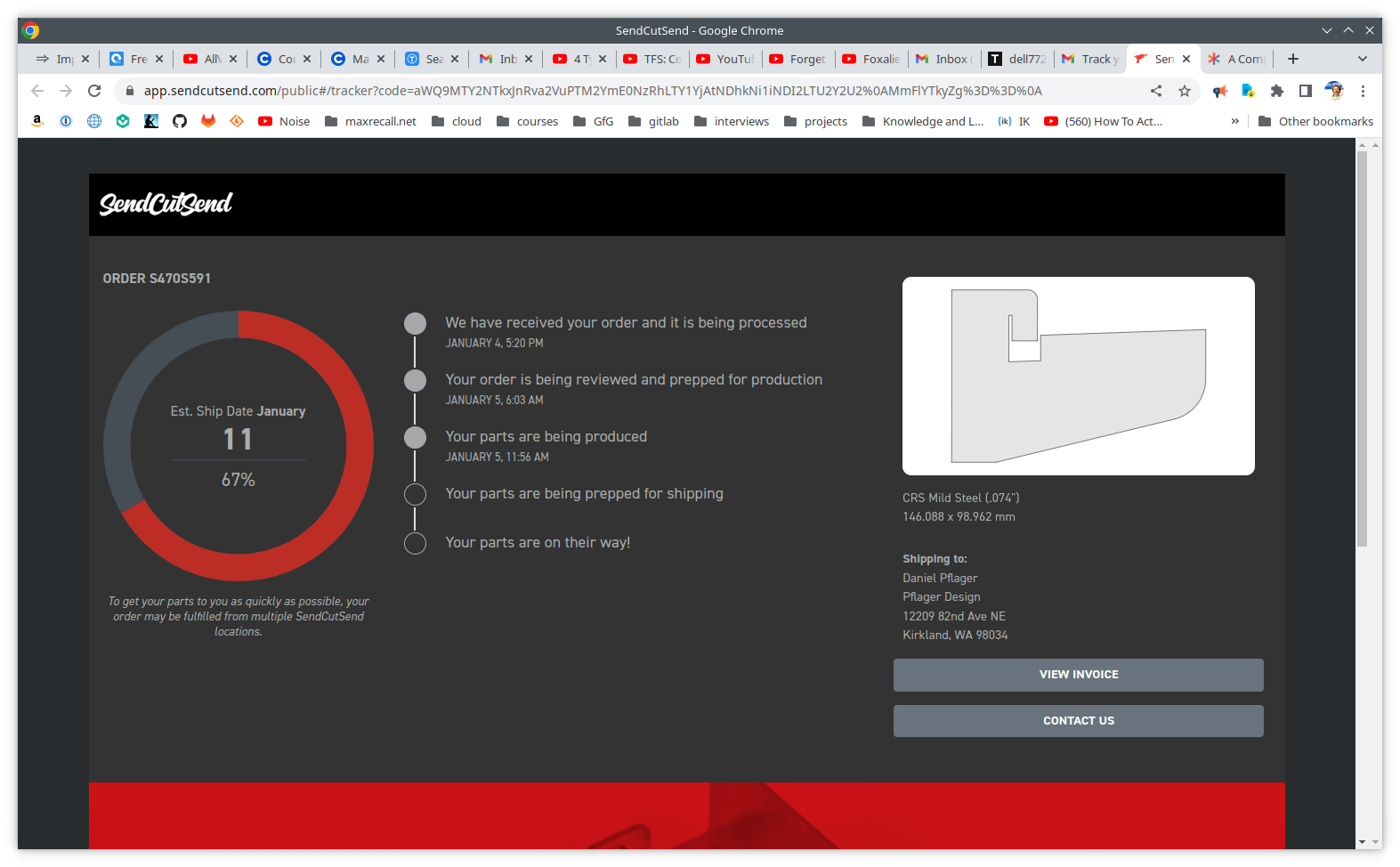
JANUARY 17 2023 Ten more prototypes from SendCutSend arrived. Very, very impressive. Total cost, including shipping $31.96. Why would I waste a dime on KOMACUT (in China).
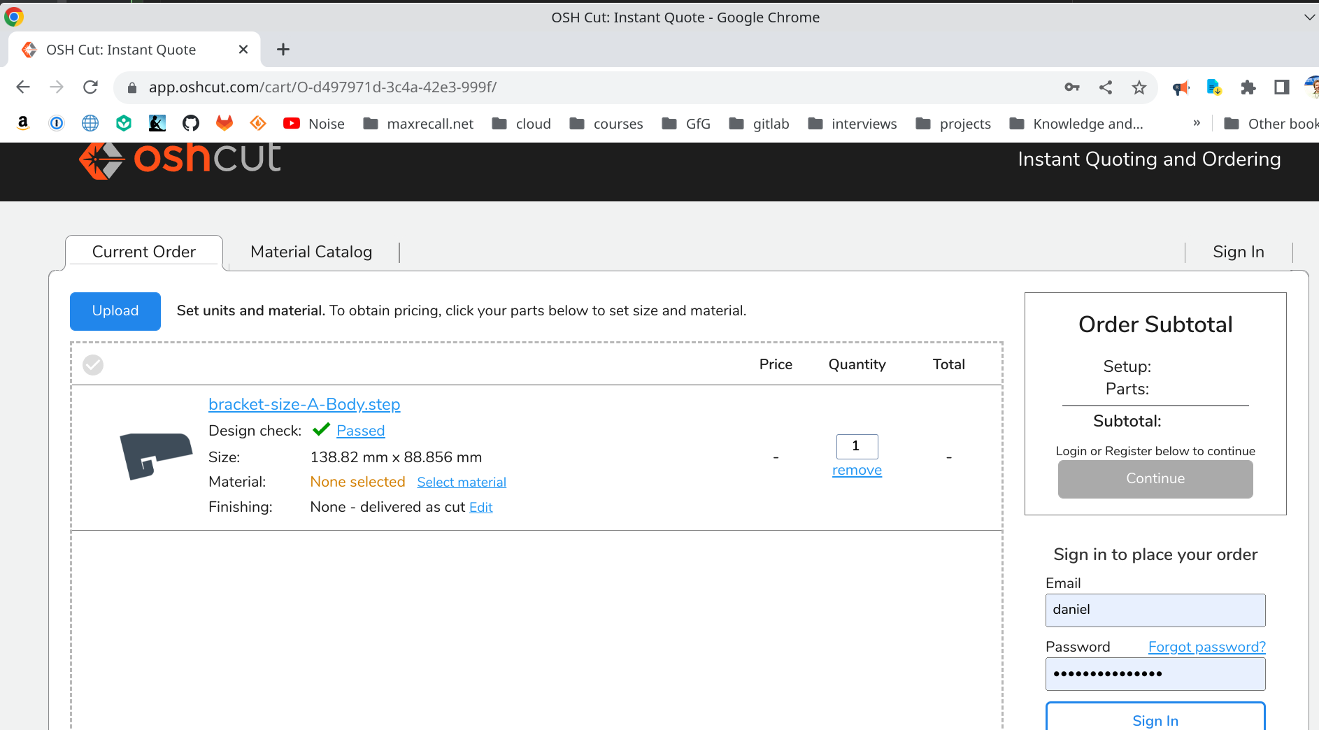
JANUARY 6 2023 One of the prototypes from OSHCUT arrived today. A bit disappointed in the packaging and the delay but the product is okay.
JANUARY 5 2023 The prototypes from SendCutSend arrived ahead of schedule on Jan 2nd, and they are great. The OSHCUT prototypes have been delayed.
Yesterday I got the new vise set up and attached to one of the garage work-tables. I then moved the bending-brake to that new vise. Here they are together.
The actual bending was much easier with the new vise. I scribed a couple of guide lines, and used them to place the piece into the brake. The results were pretty decent, but I had to bash the metal to get the shelf to fit snugly into the bracket. As a result of that, I made some adjustments to the design and submitted a new order for 10 more prototypes.
Here's what the order looks like. Can't wait.
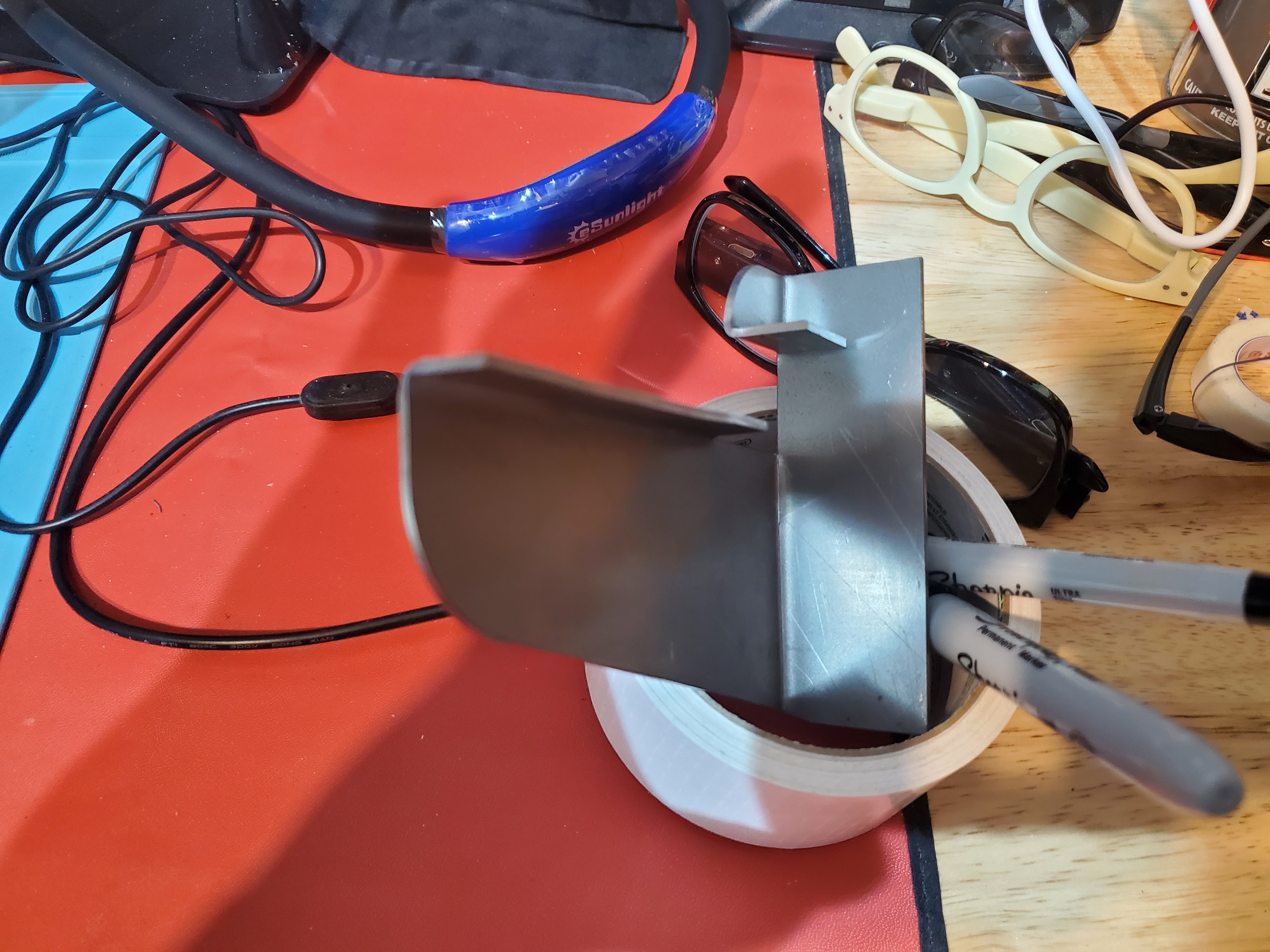
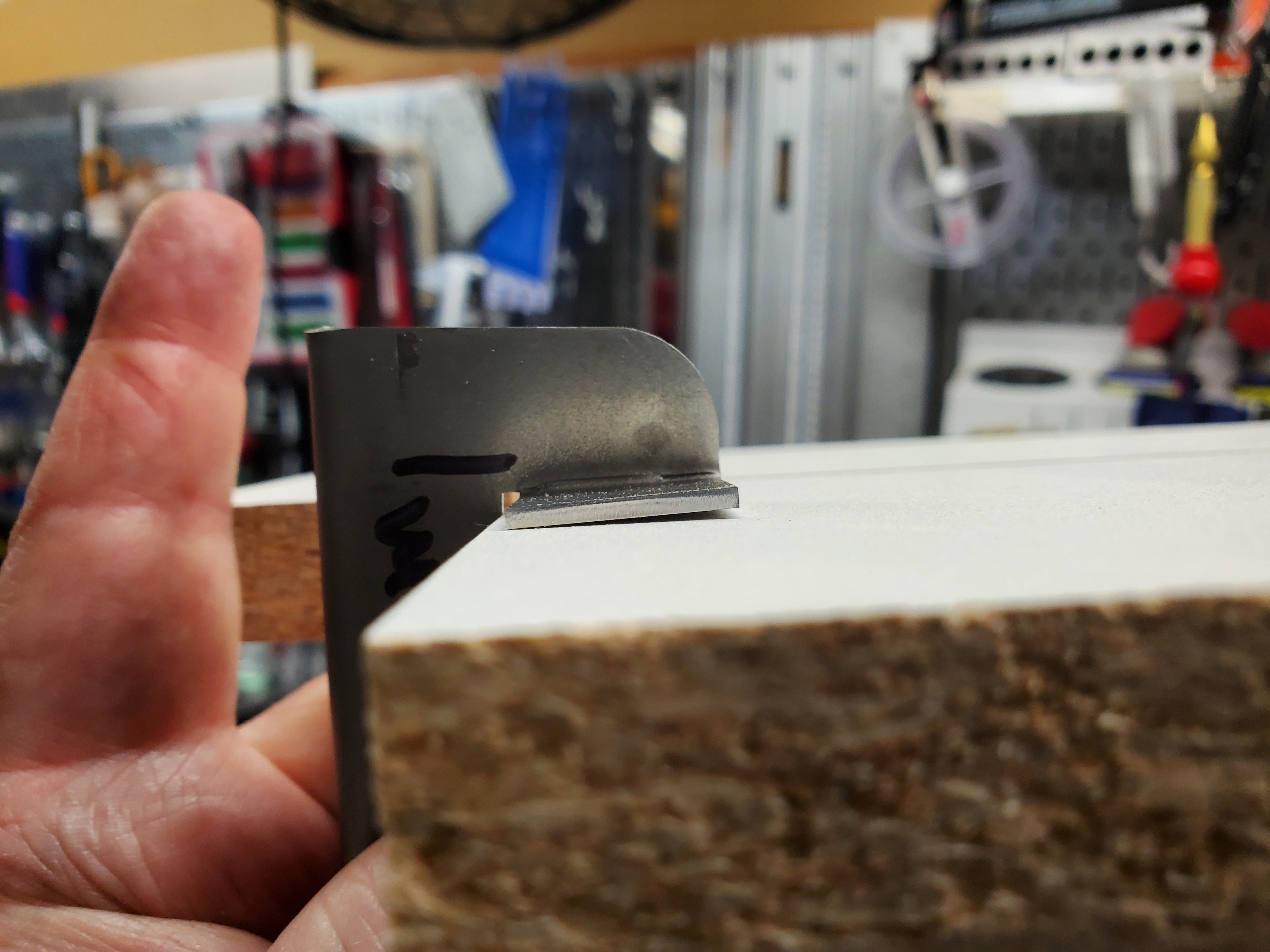
DECEMBER 30 2022 Today's project is to figure out the radius of the bend of the 1st prototype. I got the idea of using a center-punch set as a set of reference radii.


The center-punch set is stuck to the wall with magnets. I love magnets.
⇨
And here's a video of the empirical process of trying to determine the diameter (or radius) of the bend. I think the radius is more than 2.25mm.
The thickness of 14 gauge steel is about 0.8 ($\frac{5}{64}"$), which is almost 2mm. According to The Fabricator
the natural MINIMUM bend radius is 63% of the thickness - as a rule of thumb. This would put it at 1.2mm.
My empirical
measurement seems to suggest a NATURAL bend radius of more than 2.25mm.
Weirdly, this place suggests 0.03" as a rule of thumb for thicknesses of up to $1 \over 8$".
This would equate to 0.762mm. That seems kind of aggressive, and is certainly not achievable with my little vice-brake thing.
BEFORE DECEMBER 30 2022 There's a whole ton of learning that I need to do about FreeCAD. I found this playlist, which seems worth doing. Cool thing I found about FreeCAD is that it's distributed as an "AppImage", which is a self-contained Linux application with all libraries and dependencies. This has lots of potential uses.
I found a YouTube video describing how to import an image, which I used to get the scanned image of the bracket into FreeCad. That was surprisingly easy.
It was a painful process figuring out that I needed to start with a "Sketch" in FreeCAD, and I spent several wasted days getting the sketch aligned with the image. This was made more difficult by the fact that the primary video I was using was WRONG. After getting fed up with his over-confident BS, I tried some experiments of my own and eventually figured it out.
After many false starts based on YouTube videos, I figured out how to draw the lines. Eventually, I got an outline, but no matter what I did I could not get it to print to scale. That turned into a whole rabbit hole down which I spent probably two days, and a couple dozen wasted print attempts.
Having a proper scaled printed pattern on paper, I decided to use it to fabricate the first bracket prototype, rather than use the laser. That's mostly because I know nothing about how to use the laser.
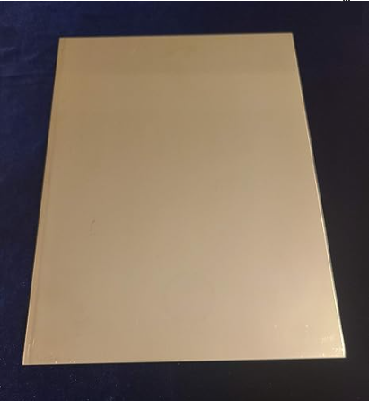
I got some 14 gauge stainless steel off Amazon, and I used spray adhesive (kind of like contact cement) to glue a paper cut-out of the pattern to the steel. Then I used a combination of a nibbler tool, angle grinder and sabre saw with a metal blade to rough in the shape. That was a frightening process, and I burned two sets of gloves with spark-spray from the angle grinder. The nibbler was pretty scary also, but I did eventually get a gnarly cut-out from the steel.
This is what the steel looks like after it's been nibbled. Those shards are sharp and very stiff. You can see the nibbling tool itself here also.
I got the remnants of the paper pattern off the steel by making a bath of odorless mineral spirits and leaving the raw bracket in it overnight. The paper pattern came right off.
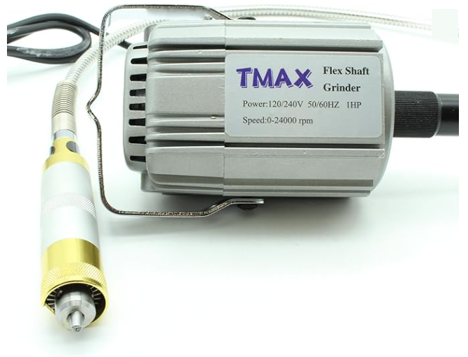
De-burring the part took several days. I'm proud of the fact that I managed to neither burn nor cut myself in the process. I used the bench grinder to round some sharp edges and take the biggest burrs off the edge. Then I used a kind of mega-Dremel that I bought from China, but that was kind of a waste. I ended up hand-filing most of it using metal files. I did get a little mini-Dremel and with some grinding and sanding attachments. Its attachments have a 2mm shaft, whereas the real Dremel has a $\frac{1}{8}"$ shaft which is slightly thicker.
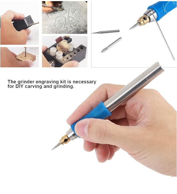
The fun part about the mini-Dremel is that it was battery powered and very portable, so I could carry the part and mini-Dremel with me and deburr while watching TV. The mini-Dremel takes AAA-size lithium batteries, and came with a charger (but not the batteries). About the time I finished de-burring the part, the mini-Dremel died. I think I killed it.
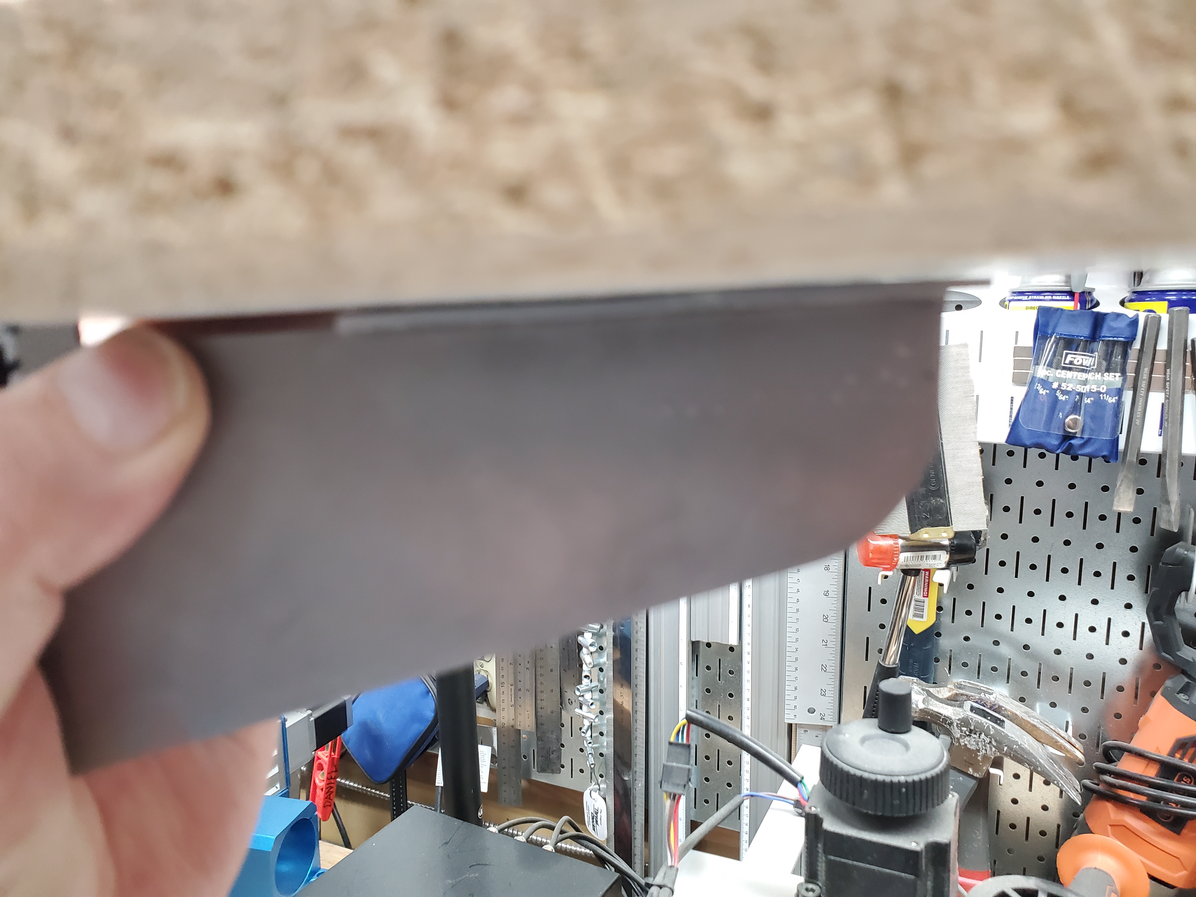
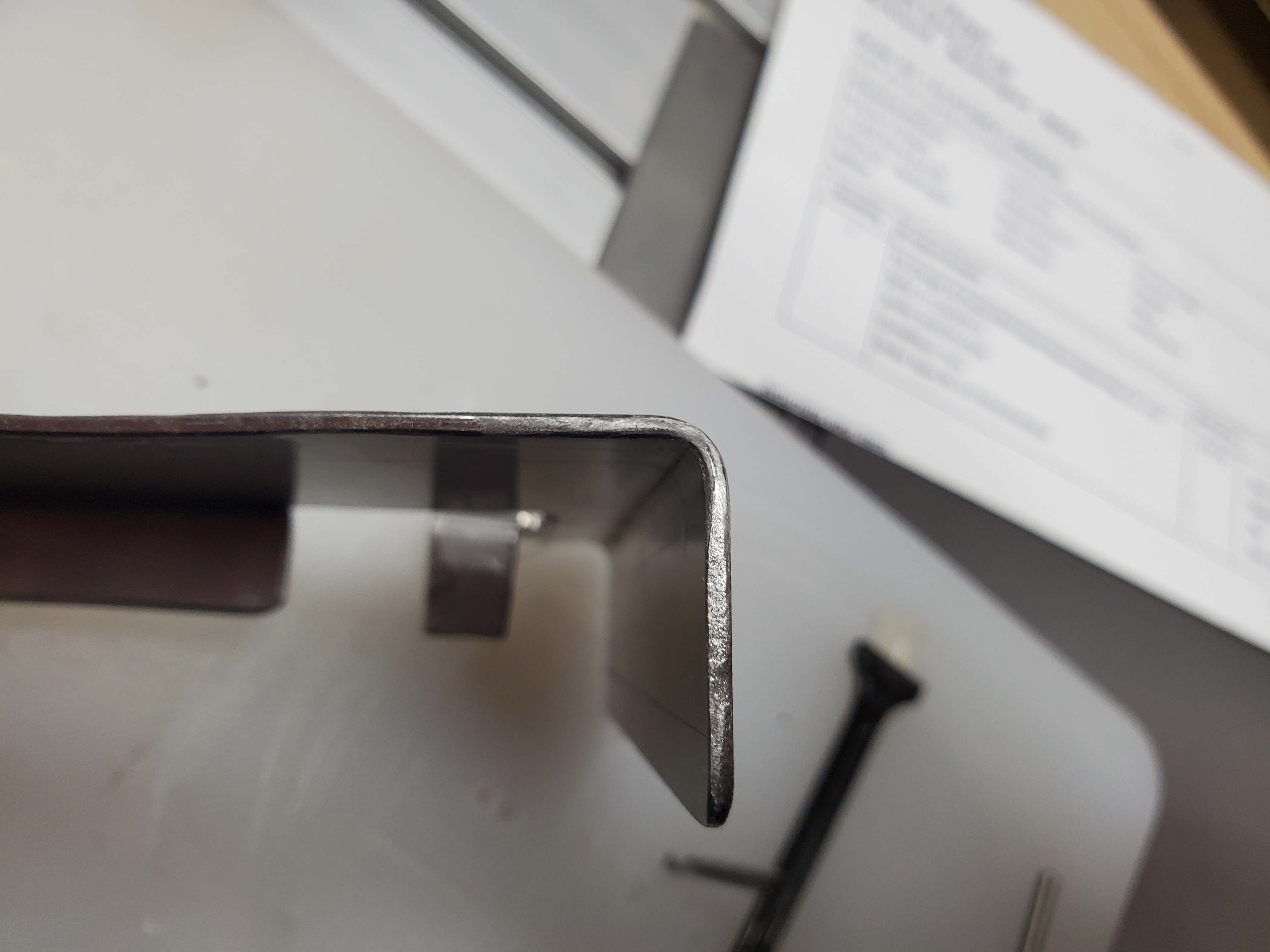
Here's what the bracket looks like so far.
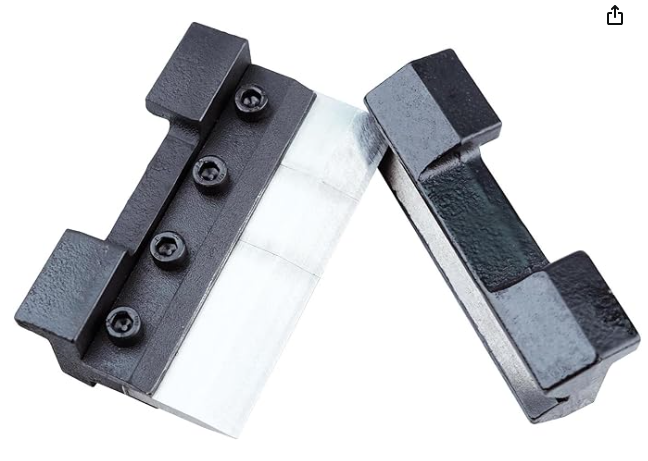
The next challenge is to bend the bracket. For that I did some research, and found that I needed a "brake". Well, they cost mega $$$, but I found a mini-brake gadget which can be used with a bench vise. I have a bench vise, so I got that gadget.
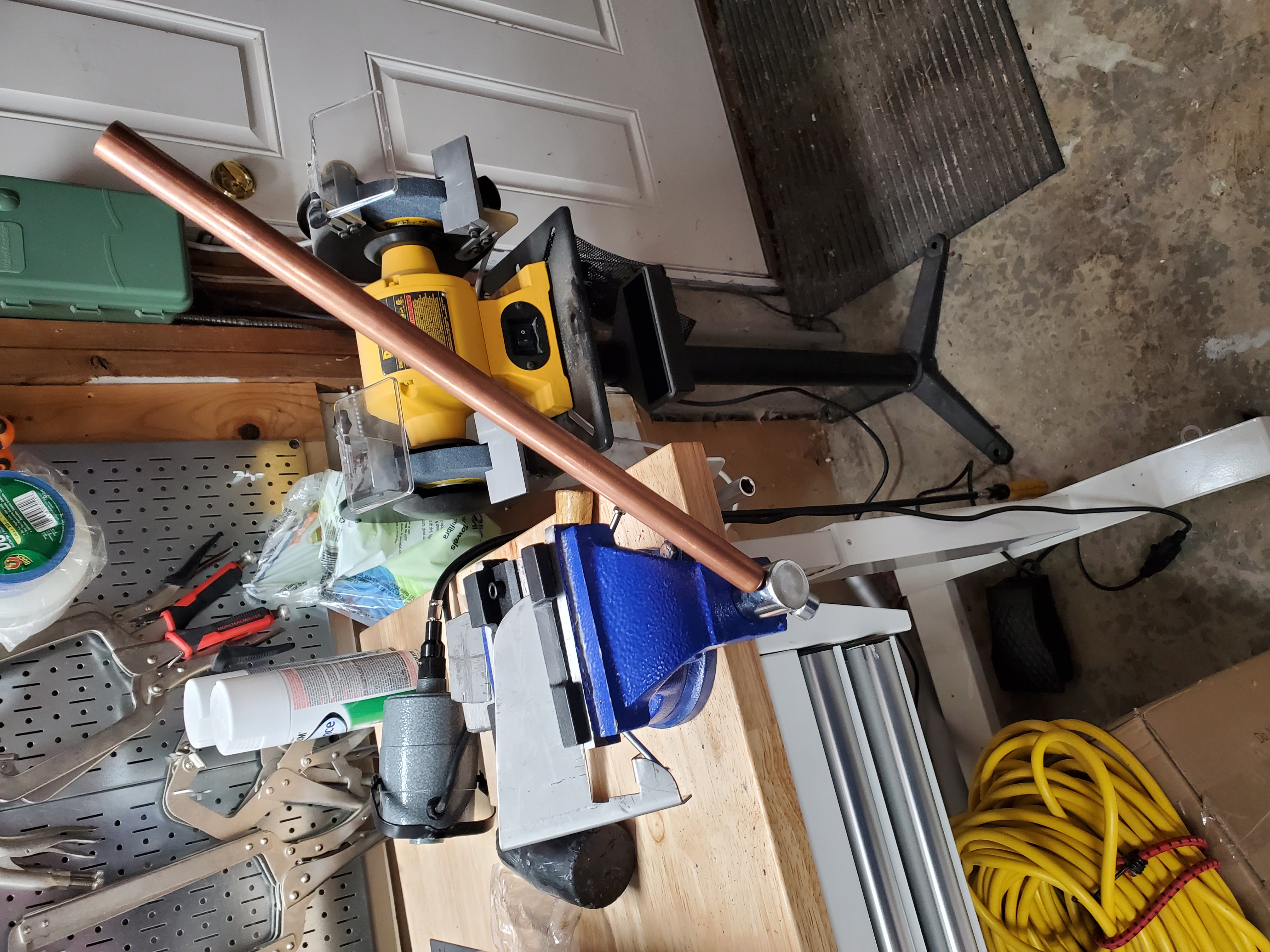
I couldn't put enough torque on the vise to get the brake to fully bend the bracket, so I used a piece of copper pipe to act as an extension to the vice's "bar". I succeeded in bending the vice's bar, but still couldn't bend the bracket fully.
So I ordered some 3/8" steel bar, allegedly stiffer than the vice's bar. I got two different types just in case. I bought two 2 foot lengths. The length allowed me to apply direct torque with both hands on either end of the bar - as opposed to both hands on one end of the vice's short bar.
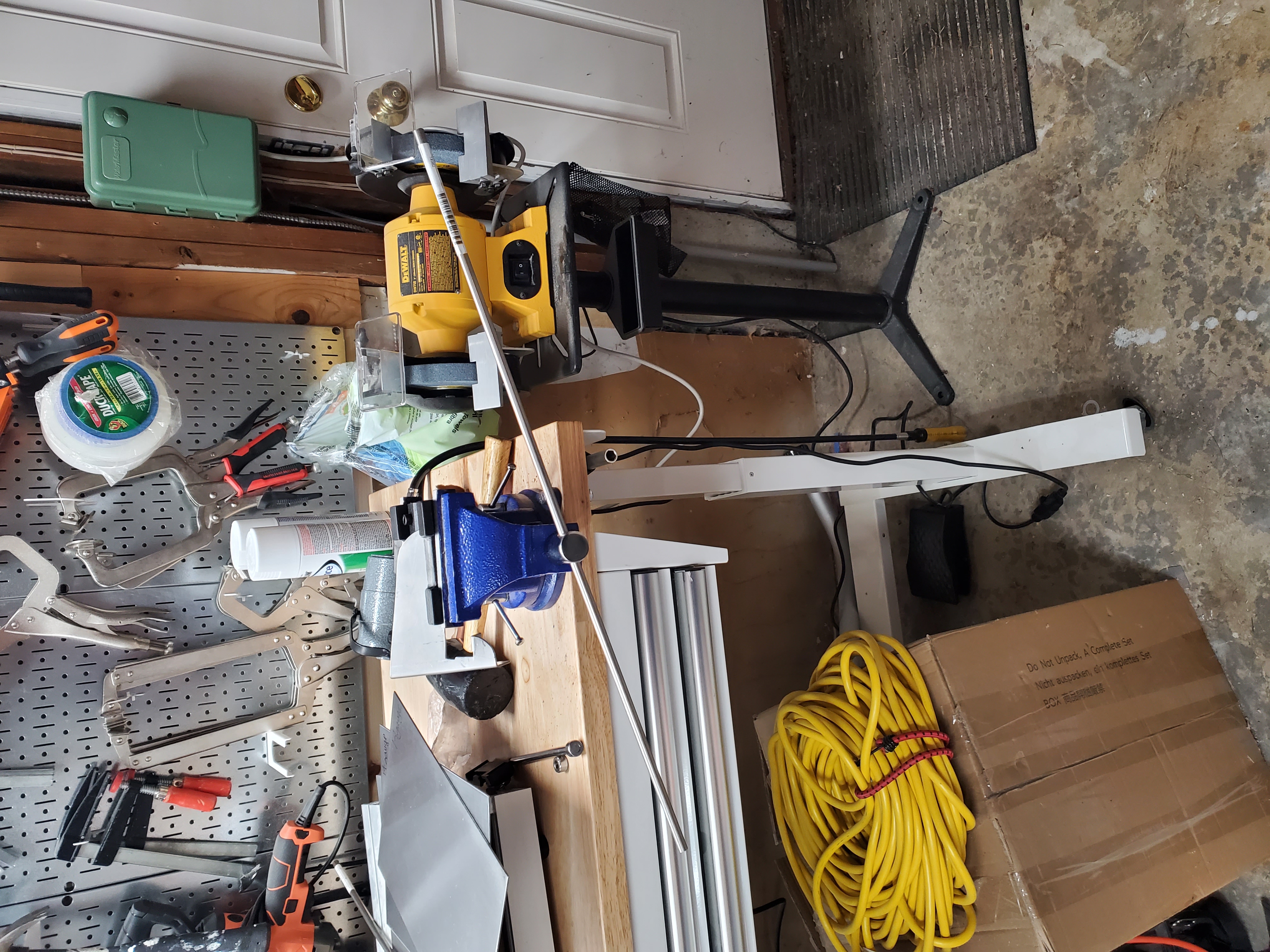
This worked, but I still managed to bend both bars in the process. There was no difference between the two bars that I could detect. In any case, the bending of the bracket was successful. I got the bars from Online Metals. One of the bars was T304 steel and the other was T316.
I learned something important about bending steel sheet. It doesn't really matter what kind of brake radius you use, the metal is going to bend at its natural radius no matter what you use - as long as the radius you use is less than the natural radius.
I attempted to do some research to determine what the natural radius of 14 gauge mild steel
is, but discovered that there is really no way to know except by experiment. That means
if I ever figure out how to put the bends into the FreeCAD model, I'll need to specify the
bend radius based on the actual material used.
That means I'll need to measure the radius
of my sample here. Not sure how to do that.
Next I decided to figure out how to use my little 3018 5.5 watt laser to maybe etch the pattern directly onto the steel.
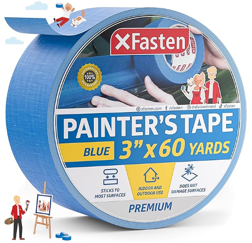
That turned into another giant adventure. So far the most success I have had is to use super-wide blue painters tape and etch the pattern using the laser into the tape. This results in a blue pattern affixed to the steel.
Working with the blue tape pattern turned out to be a pain. I decided to try a steel-cutting blade for my little 4 1/2" circular saw. That resulted in a broken blade, and a gummed up edge on the part. Not a success. I used the sabre saw to cut out the other features, but by this time the tape had almost totally detached from the steel.
One kind of cool thing was that the laser did seem to leave a thin line of black carbon on the steel from where it has burnt the tape, so in some places I could just about make out where the pattern is.
The burn/marking with painter's tape is definitely worth some more experiments.
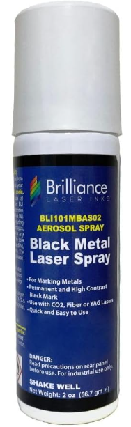
A bit of research revealed that there is a commercial product, allegedly suitable for marking on steel, so I ordered some of it. I think I'll try to reverse engineer it, because it seems to cost way too much.
Some of the sites I saw during the research also recommended Dry Moly as an option for marking on steel, so I ordered that too:


Since I'm planning to spray paint this thing white anyway, another option might be to try to etch into Rust-Oleum.
It occurs to me that laser printers fuse plastic "toner" onto paper. I wonder if that can be done on steel.
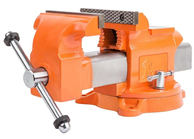
Clearly, my vise problem is not going away. I need a heavier vise.
Meanwhile, I did a slight redesign on the bracket. I also found that I could get cut parts relatively inexpensively from a couple of online sources, so I decided to give them a try.